Drawings
Overview
The drawing pages makes it possible to view and modify connections between components in a way that is identical to how circuit diagrams are made. Since the symbols are made to be descriptive of the functionality of the components, the drawing view gives a clear overview of how the system works and how the ports are connected.
Note
When creating your own components, make sure to add a symbol if they have ports, so they can be used in the drawing view.
Drawing pages
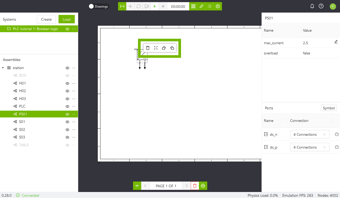
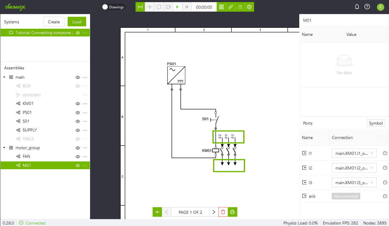
When you are in the workspace and have a system loaded, you can switch to the drawing view by pressing the switch on the left side of the toolbar.

When you enter the drawing view, a new toolbar will appear in the bottom of the screen with options related to the drawing pages.

Going from left to right, the buttons are:
-
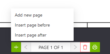
Add Page: Opens a second menu, see below, where the user is asked where to put the page. Add new page adds a page at the end of the drawing. Insert page before adds a page before the current page. Insert page after adds a page after the current page.
-
Previous / Next Page: Use the arrow buttons to navigate the drawing.
-
Remove: Removes the current page from the drawing.
-
Print: Generates and downloads a PDF of the drawing.
Adding components
Components are added to the drawing page by drag-and-drop from the Assemblies panel.
Note
Using the same component on multiple pages is allowed, but it is not allowed to have the same component pair on multiple pages.
Position, rotate and resize
Components can be positioned by dragging them around, and scaled, rotated and removed by pressing them to bring up the context menu.
Connections
Connections can be modified in the drawing view, which will give the same result as if they were connected from the Ports panel.
Making connections
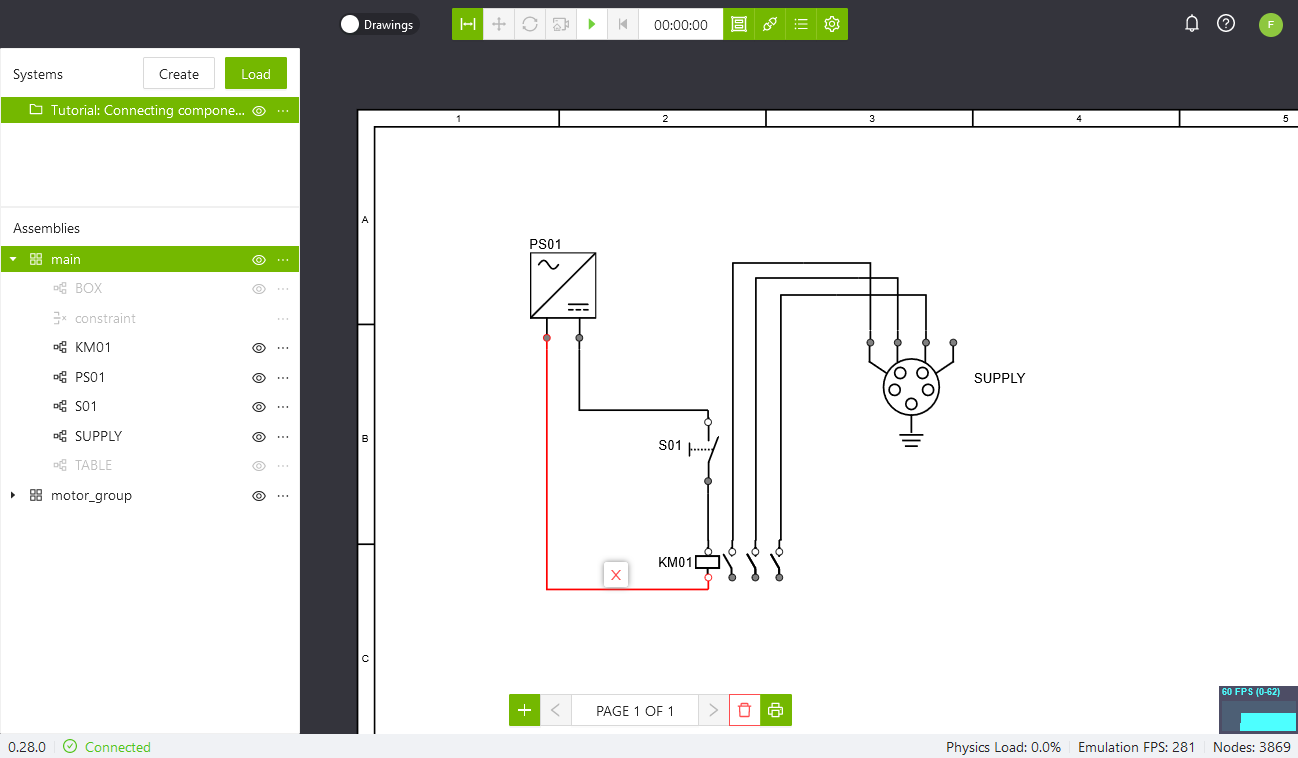
In the drawing mode there are two ways to create a connection between two ports. The first is to click-and-drag between the two ports in th drawing. The other is to right-click on an input port and use the menu to select the corresponding port. This will create a line between the ports, meaning that they have been connected. Both ways is shown in the .gif below.
Adding Pivots
To enhance the readability in the drawing pivots can be added to a connection line to control the path. Pivots is created by double-clicking on a line. Two pivots will be created, one to control the x-position and one to control the y-position. Drag the pivots to get the desired path.
Connection references
Connections to a port of a component that is not added to the current page will be shown as an arrow.
Connections to a port of a component on other pages will also be displayed with a reference annotation with page number and coordinate of that connection. By double-clicking the reference the drawing view will move to the referenced page.
Removing connections
To remove a connection, right-click either on the arrow, or on the line that indicates the connection and then the red x symbol.
Add Note
Notes can be added to the drawing page. To add a note, right-click on the page and select Add note. Double-click the text field to edit the text. The note object can be moved, scaled, rotated and deleted in the same way as a component symbol.